|
First, some background.
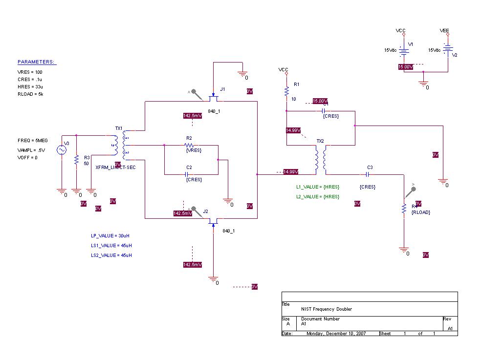
The members of time-nuts suggested that the Fury Interface board might benefit from using a 5MHz OCXO instead of the 10 MHz, that is specified. I agree with this since I have a bunch of different 5MHz devixes that I'd like to test with the FURY. Bruce Griffiths suggested that I use the NIST frequency doubler in the paper: NIST_Ultra-High_Stability_Synthesizer_For_Diode_Laser_Pumped_Rubidium.pdf This paper, has a tiny schematic of the doubler (above the chart on Page 3, Figure 3) so I had to do a bit of digging to get out the needed parts. This paper: Superimposing_Low-Phase-Noise_Low-Drift_Instrumentation_Techniques_On_RF_Design helped shed some light on the parts. The critical part is the Siliconix Dual FET. Siliconix, it turns out, was bought by Linear Systems and they make a similar part: LS840. Here is a copy of the datasheet. This part is in production and they provide a PSPICE model which is what I used to model the circuit. So, here is the schematic:
|
|
And here are the THD results:
	FOURIER COMPONENTS OF TRANSIENT RESPONSE V(VOUT)

	 DC COMPONENT =   8.480375E-04

	 HARMONIC   FREQUENCY    FOURIER    NORMALIZED    PHASE        NORMALIZED
		NO         (HZ)     COMPONENT    COMPONENT    (DEG)       PHASE (DEG)

		 1     1.000E+07    4.106E-01    1.000E+00    1.464E+02    0.000E+00
		 2     2.000E+07    9.307E-04    2.267E-03    4.276E+01   -2.500E+02
		 3     3.000E+07    7.535E-04    1.835E-03    2.117E+00   -4.370E+02
		 4     4.000E+07    5.460E-04    1.330E-03    2.871E-01   -5.852E+02
		 5     5.000E+07    4.382E-04    1.067E-03   -7.983E-01   -7.327E+02

	TOTAL HARMONIC DISTORTION =   3.378344E-01 PERCENT
Not bad!
|
|
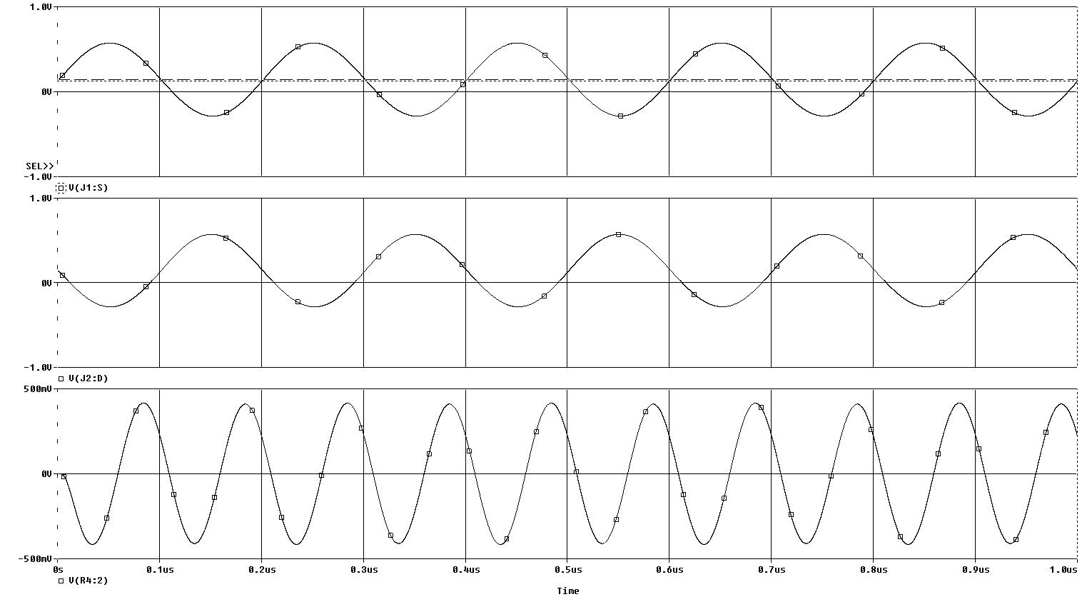
And here are the appropriate waveforms:
|